Automated chickenfeeder
Start of the projectThe idea of this project originally came from Tim (thanks mate for finding me a new project).
Allthough I have to visit my chickens every day (to get the eggs) I want an automated feeder system. Why? ..... just because it's cool.
I know there are many feeding systems available in the pet shop but I don't want them to have access to the specialised food the whole day. Exposing them to an unlimited supply of grains, corn, ... would stop them from eating my kitchen waste (and that's why we bought them in the first place).
My chicken house:

How does it work
The idea is to mount a wooden plate in the chicken house to create a silo. At the bottom of that silo is a transport system to get the grains to the feeding place.
Materials and tools needed
Materials
- Wooden plate
- Piece of wood (about 5cm*5cm*25cm)
- Slowly rotating motor. I used a 12V motor with a reduction system from an old copier. It is imporant that it has a low speed (about 100 RPM) and a high torque
- Lots of screws
- Metal wire
- Small piece of tube, to connect the drill to the motor (both the shaft of the motor and the drill have to fit in the tube)
- clamps to fasten the tube around the shaft and drill
- Plastic tube to transport the food
- Drills
- Saw
- Screwdrivers
- Workbench

Transport system, first prototype
The first system I made used the actual drill to transport the food.
The first test was very succesfull, the drill was able to transport the food and didn't get stuck at any point.
Making the actual model was a different story though. Since I was affraid of the wooden block wearing out by the drill I used a piece of tropic hardwood.
On small remark though: tropic hardwood is HARD!!!
It took about 30 minutes to drill about 10cm deep. With smoke coming out of the wooden block and the power drill, something had to go wrong. So 5cm before we got through the block my power drill passed away. Thanks to a professional power drill we were able to finish the job so I guess this is where you see the difference between a 250 Euro powerdrill and a 29 Euro one :-)
Transport system, improvement
Using the drill to transport the food had a very high throughput of food but there had to be a drawback. When a piece of grain or stone got caught between the drill and the wood the whole system jammed and I had to turn it back manually to solve that. In real life this would mean my chickens would starve. The new transport is system is so simple I could believe it would work until I saw the whole system running.
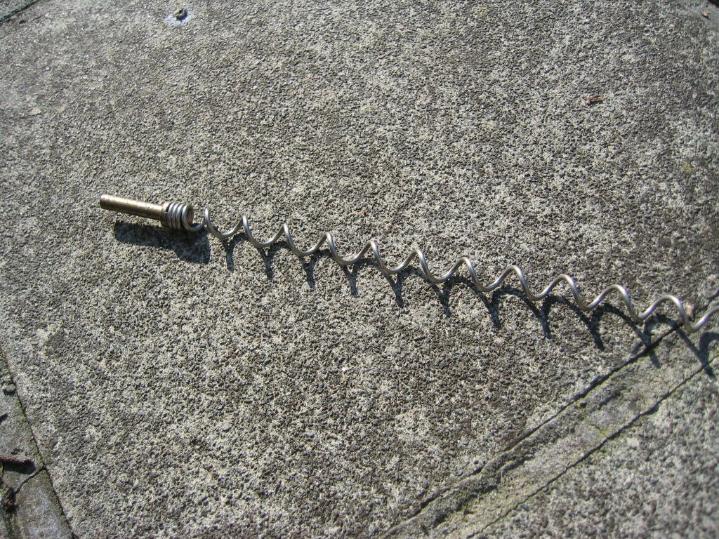
Instead of the drill I have a spiral made from metal wire that is about half the diameter from the hole in the block. It runs freely in the hole without any resistance and pulls the grain out at a steady rate. The throughput of food is less but I can let it run for a longer time to get the correct amount.
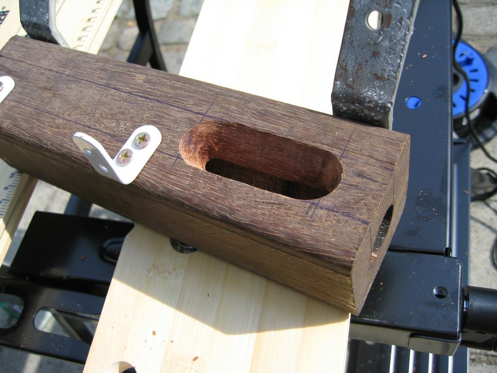
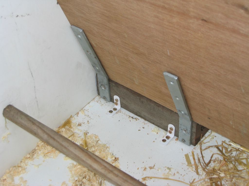
This is the block of wood that is the core of the system:
The grain will fall in the slot you see on top and it will be transported to the hole at the right side. There are already mounting brackes in place to make the installation quicker.
This is the spiral:
construction and installation
A sunny sunday is all it takes to go shop for the needed tools and install the system.- Drill a hole of the same size in the sidewall of the house exactly where the transport tunnel will come

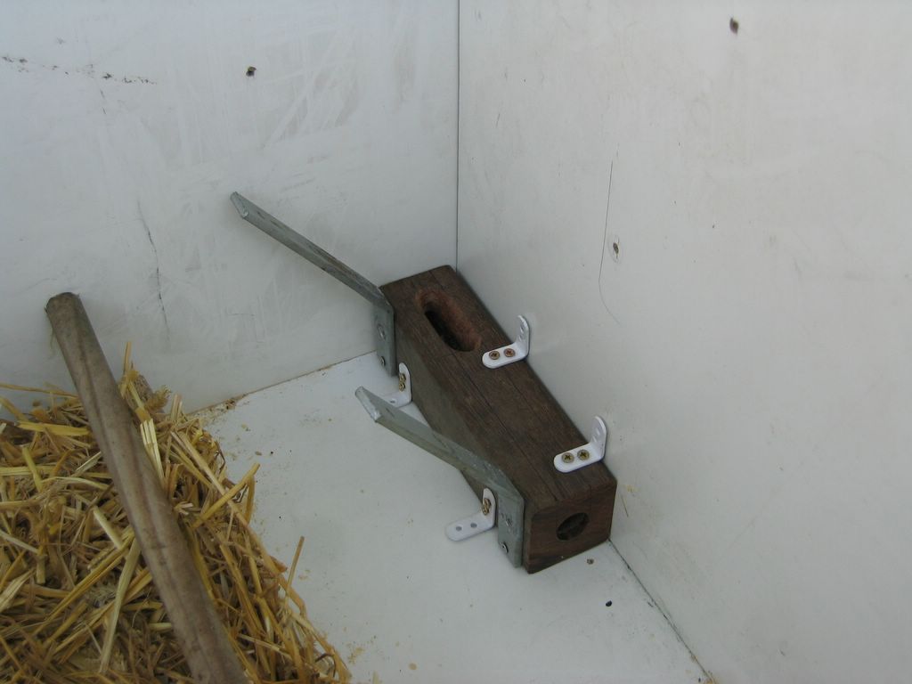
- The transport block is installed in the corner of the house using L-shaped mounting plates. It is needed to drill a hole in the hardwood first where the screws will come because getting a standard screw in is impossible.
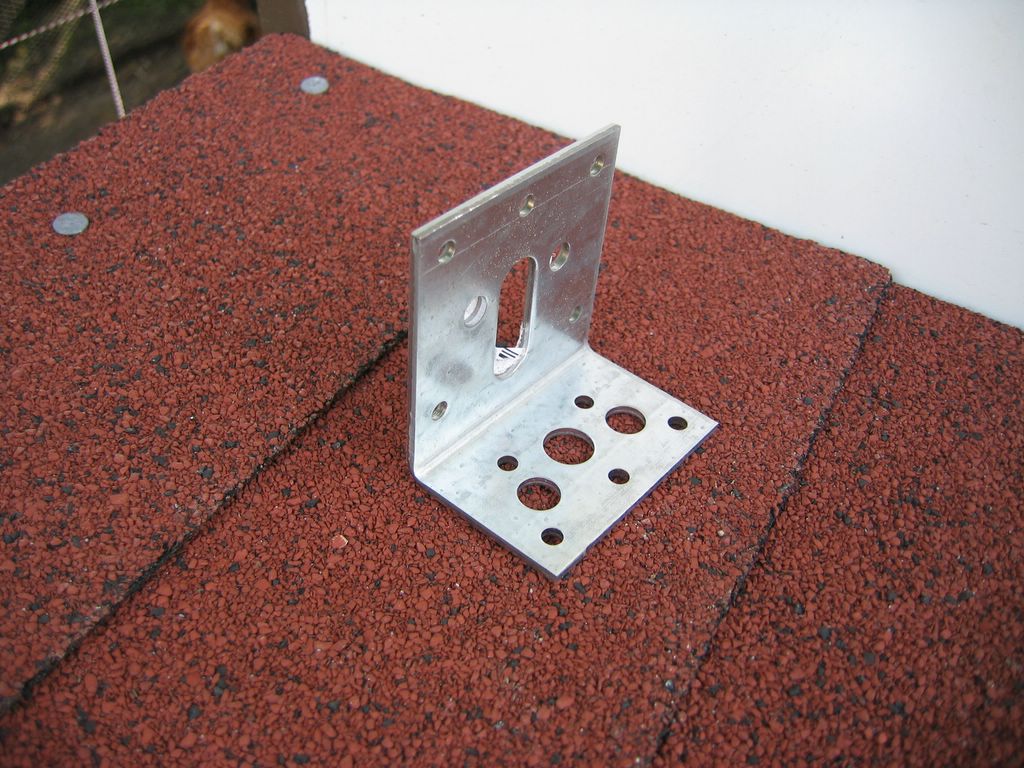
- The motor is be mounted against a large L-shape mounting plate that already had a slot of 10mm width where the shaft fits in. I had to add a small piece of wood because the part where the shaft came out was slight bigger then 10mm.
- A small piece of tube and two clamps will firmly connect the spiral to the shaft of the motor.
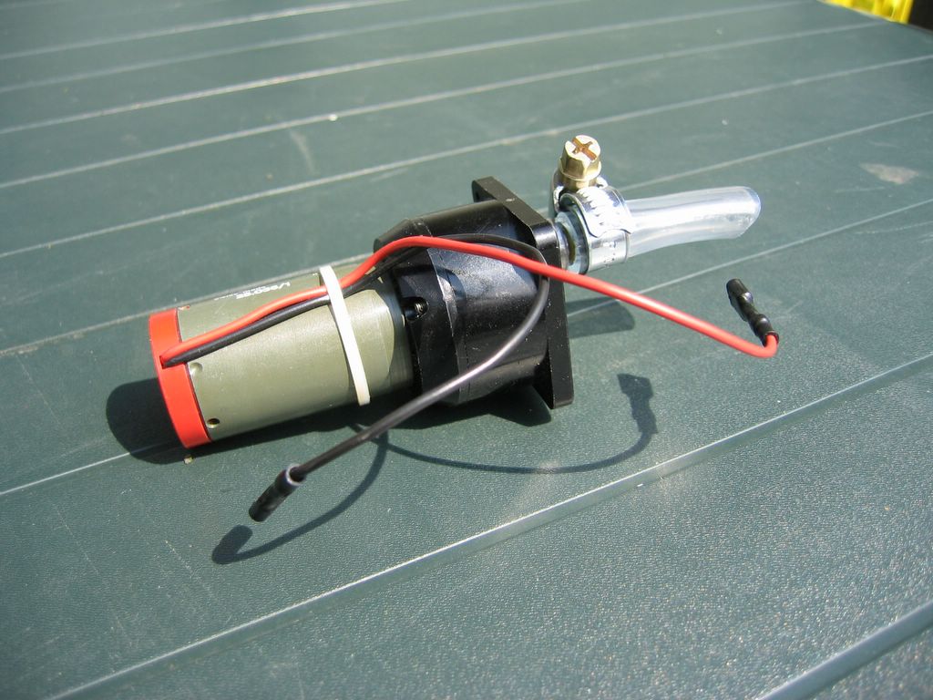
Closeup on the motor:
This is the spiral connected to the motor: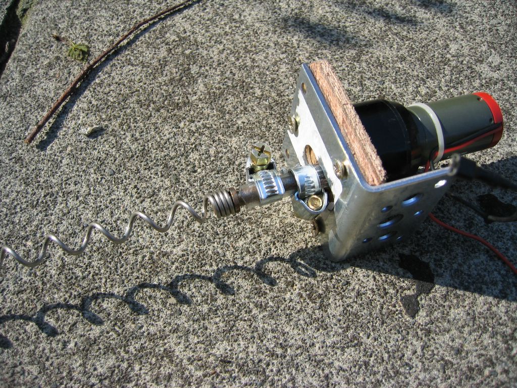


- The spiral is passed throught the tunnel and the motor is mounted so there is enough space to let the clamps turn freely. Because we used platic tube to connect them, it can buffer any variations in the movement.
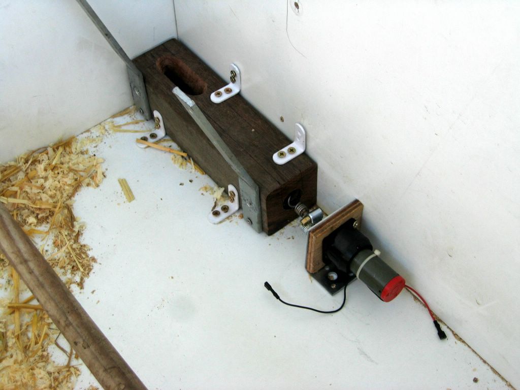
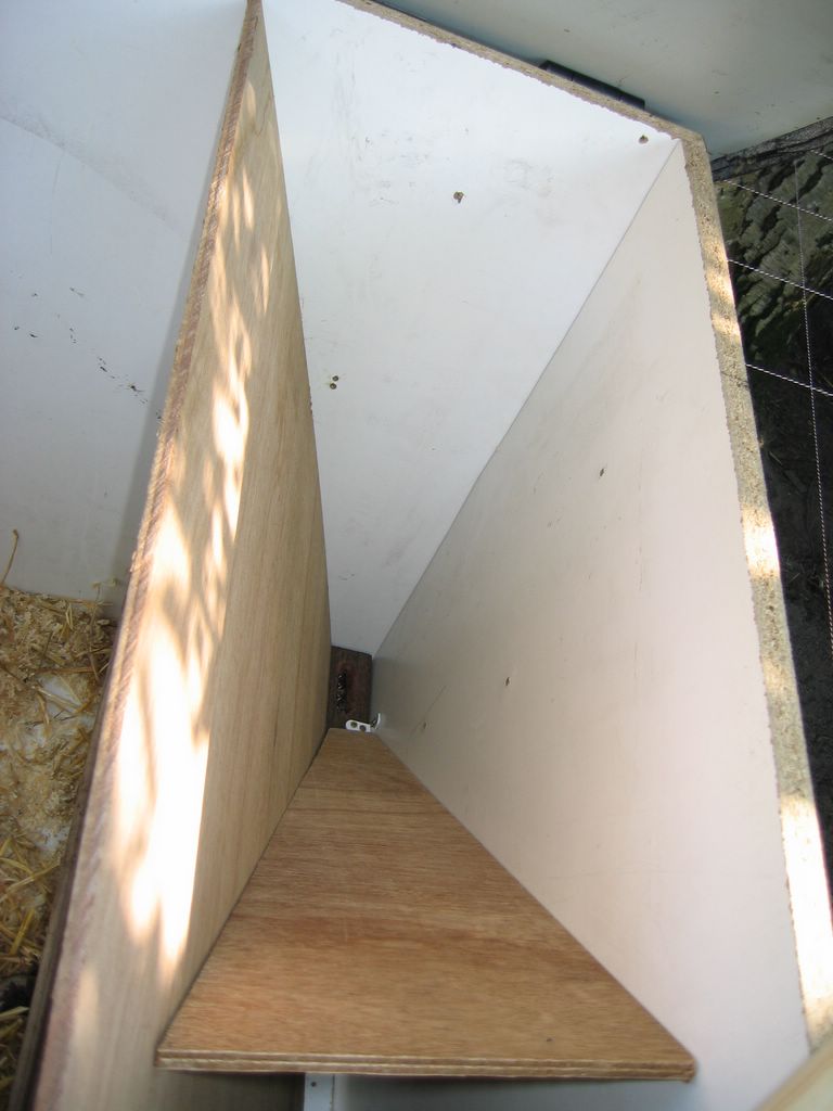
- At the sides of the transport block there is are two L-shaped mounting plates that were bend to a much bigger angle of about 165°. These will hold the sideplate to create the food silo.
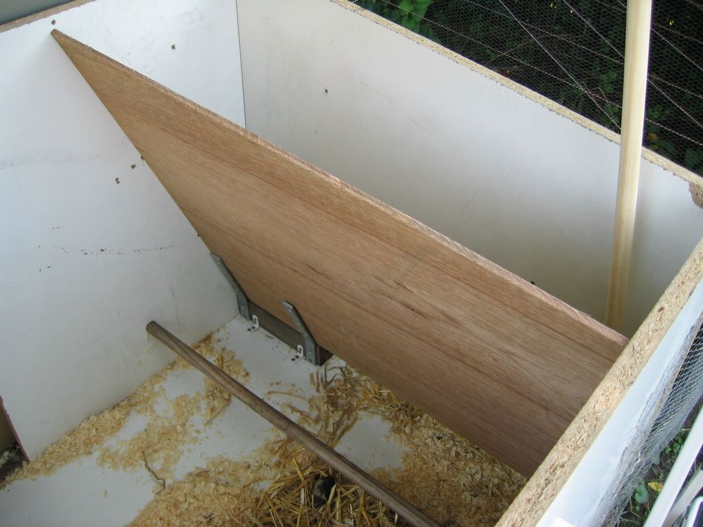
- Inside the silo a triangle is installed to bring all the food to the transporter


Transporter in action
This is a picture taken with the motor turned on. It takes about 10 minutes to supply 250g - 300g of food. A plastic tube will be mounted over the hole to guide the food and protect the chickens from hurting themselves

The controller
What's nice hardware without some software behind it to make it all happen?
I had to find a controller that would run independant, consume almost no power, turn the system on at the desired time and turn it back off once enough food was delivered.
After a few (silly) ideas I discovered a digital timer you could plug in an outlet to control stuff (like lamps or coffeemachines)
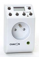
Inside the whole system consists of 3 parts: the power plugs, the digital part and the small circuit board that changes 240V AC to 24V DC and 3V DC and switches the relay.
The 24V is used to drive the relay so we won't be using that, the 3V is used to power up the digital part and that is what we need.
Since the current consumption of the motor is very low I can switch it using a transistor only. I used a BC547C (NPN transistor) because they can draw 100mA and my motor only needs about 30mA.
The internals of the timer are completely stripped out and only the digital part remains. 3 wires are coming out of that PCB: 2 for power and 1 control line. It took my a while to discover how the control line was working but after I while it became clear that it was connected to ground through a transistor when the system was off and disconnected from ground when the system became active.
To use that signal for controlling a transistor I only needed to add a pull-up resistor between the positive supply and the base of the transistor.
In my first design I made the 3V using an LM317 (adjustable voltage regulator) . The design looked like this:

This cicuit worked fine but it had one major disadvantage, it consumed about 20-25mA. This is too much for a system that has to run on batteries.
WARNING: INSIDE THIS SYSTEM ARE MANY PARTS CONNECTED THE THE MAINS. DO NOT TOUCH ANYTHING WHILE THE SYSTEM IS CONNECTED TO THE POWER. IN FACT, DO NOT OPEN IT AT ALL UNLESS YOU ARE 100% SURE OF WHAT YOU ARE DOING. I AM IN NO WAY RESPONSIBLE TO WHAT YOU DO TO YOURSELF, RELATIVES OR THE TIMER
Reducing the power consumption
The next challenge was to get the power consumption to a level where it could run on batteries or solar panels.
Making a small calculation I found that I lost about 177mW of power in the LM317. That was an efficiency of less then 26% (later I found that it was even worse than that).
Linear power regulators have the problem that they transform the complete voltage difference between input and output to heat. The obvious solution was a switching power supply.
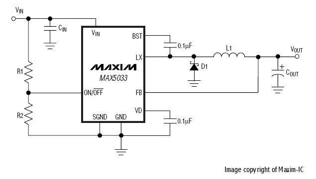
After some struggle I managed to get a MAX5033. It requires some, easy to get, external components and should have a much lower consumption.
This is the diagram I copied from the maxim datasheet that shows how the chip needs to be configured:
The result of this chip were magnificent, the consumption dropped to 2.5mA !!!
It's finaly working !!!
With the new controller in place the system should work for about 200 days on a 16Ah battery. I will add solar panels as well in the future but for now I'm happy the way it works.
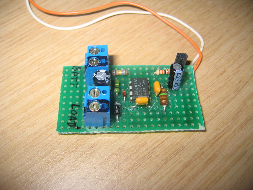
On the photo you can see the MAX5033 with the components to transform the power from 12V to 3.3V.
On the top right is the transistor that switches the motor, there is also a diode in reverse over the motor connection to absorb any reflow of current. The trasistor BC547C can draw 100mA and since my motor only consumes around 30mA this is more then enough. When you want to use a bigger motor you might need to use another transistor or a relay.
Right now the system turns on at 8.05h in the morning and runs for 11 minutes, that way the chickens get the same amount of food as before.
I will add some pictures later of the outside tube that transports the food.
If you need any additional information, have some comments or want to say something, feel free to leave a comment.
posted by Miyagi @ 21.8.05
71 comments
![]()
![]()

